This is what I use on my Pi4
[all]
#dtoverlay=vc4-fkms-v3d
#dtoverlay=i2c-gpio,bus=6,i2c_gpio_sda=23,i2c_gpio_scl=24,i2c_gpio_delay_us=2
dtoverlay=i2c6,pins_22_23
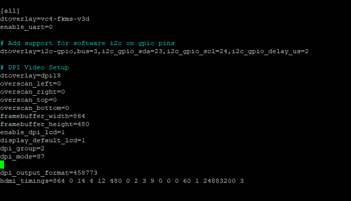
dtoverlay=dpi18
#dtoverlay=dpi24
overscan_left=0
overscan_right=0
overscan_top=0
overscan_bottom=0
## Use a custom DPI mode
dpi_group=2
dpi_mode=87
enable_dpi_lcd=1
display_default_lcd=1
## Should this really be 864x480? Native for the DMD should be 640x360
#framebuffer_width=864
#framebuffer_height=480
framebuffer_width=640
framebuffer_height=360
### https://www.raspberrypi.org/documentation/hardware/raspberrypi/dpi/README.md
## These are for dpi18
dpi_output_format=458773
#dpi_timings=864 0 14 4 12 480 0 2 3 9 0 0 0 60 1 24883200 3
dpi_timings=640 0 14 4 12 360 0 2 3 9 0 0 0 60 1 13824000 3
## These are for dpi24
#dpi_output_format=458775
#dpi_timings=864 0 14 4 12 480 0 2 3 9 0 0 0 60 1 24883200 3
To use it on a Pi0, you would want to comment the dtoverlay=i2c6,pins_22_23 line and uncomment the dtoverlay=i2c-gpio,bus=2,i2c_gpio_sda=23,i2c_gpio_scl=24,i2c_gpio_delay_us=2 line. Note that I’m using I2C bus 6, not 3, because on the Pi4 there’s a hardware I2C bus on those pins. That doesn’t exist on the Pi0 so you have to use the GPIO driver instead. If you want to still use bus 3, change the bus paramter on the i2c-gpio dtoverlay and change the BUS= Environment variable below.
Then create /etc/systemd/system/dlp.service as
[Unit]
Description=DLPDLCR2000EVM setup
[Service]
Type=oneshot
RemainAfterExit=yes
# Which I2C bus to use
Environment="BUS=6"
# Set resolution to 640x360
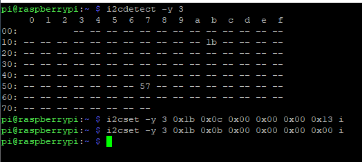
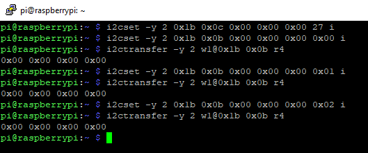
ExecStartPre=/usr/sbin/i2cset -y $BUS 0x1b 0x0c 0x00 0x00 0x00 27 i
# All LEDs on
ExecStartPre=/usr/sbin/i2cset -y $BUS 0x1b 0x16 0x00 0x00 0x00 0x07 i
# Set input to parallel bus
ExecStart=/usr/sbin/i2cset -y $BUS 0x1b 0x0b 0x00 0x00 0x00 0x00 i
# Set input to test pattern
ExecStop=/usr/sbin/i2cset -y $BUS 0x1b 0x0b 0x00 0x00 0x00 0x01 i
# Set test pattern to black
ExecStopPost=/usr/sbin/i2cset -y $BUS 0x1b 0x11 0x00 0x00 0x00 0x01 i
# All LEDs off
ExecStopPost=/usr/sbin/i2cset -y $BUS 0x1b 0x16 0x00 0x00 0x00 0x00 i
[Install]
WantedBy=multi-user.target
After making those changes, reboot, and run sudo systemctl start dlp to configure the DLP2000. If you want this to happen on boot, run sudo systemctl enable dlp. Run sudo systemctl stop dlp to configure the DLP2000 to a black screen, and turn off the LEDs.
Also note that I’m using 640x360, the native resolution of the DMD in the DLP2000, rather than 864x480. Some software may not like the lower resolution as much, but it means the DLP2000 doesn’t have to rescale the image. It also means less data being sent per frame, so signal integrity is a little better with flying wires.


 .
.