Mick can you help me please?
Hello, glad that someone used my update to the solution. Do you have the color banding issue? I really don’t know how to get rid of it.
You may try to enable fkms in config.txt
So, I’m pretty new to raspberry pi, and I’ve been beating my head against my desk for a few days now.
Basically when I add:
dtoverlay=i2c-gpio,i2c_gpio_sda=23,i2c_gpio_scl=24,i2c_gpio_delay_us=2
dtoverlay=dpi18
overscan_left=0
overscan_right=0
overscan_top=0
overscan_bottom=0
framebuffer_width=854
framebuffer_height=480
enable_dpi_lcd=1
display_default_lcd=1
dpi_group=2
dpi_mode=87
dpi_output_format=458773
hdmi_timings=854 0 14 4 12 480 0 2 3 9 0 0 0 60 0 32000000 3
To my config.txt file and reboot, the screen doesn’t change at all, and I can’t ssh into my raspberry pi zero w.
If I delete what I added in, the screen still shows the DLP splash screen like normal, but I’m now able to ssh back into the pi.
I thought maaaaaybe it could be windows carriage return, but I’m pretty sure I removed those.
Anyone have any ideas?
So I narrowed it down to just this line that seems to be barfing things. If soldering is poor, or I wired this wrong, could that cause my raspberry pi to crash and thus prevent me from being able to ping/ssh?
Are you using Mick’s board, or everything up yourself?
If you enable only the i2c-gpio dtoverlay line, commenting out or deleting the rest of the new lines, and reboot without the board or projector attached, does your Pi boot normally?
Everything myself. I have a pi zero w, I soldered the pins and hooked them up to the DPL2000 projector. I did the headless boot, and I’m able to ssh into the pi.
If I comment out the other lines and just leave ic2-gpio line, then reboot, I’m no longer able to ssh into the pi and nothing changes with the screen. It still shows the default DPL2000 splash screen.
Thank you for taking the time to respond to my post by the way, I’m pretty new to this and I appreciate the help.
Are you able to connect a monitor to your Pi’s HDMI port to see if there’s anything indicating the problem? Just enabling the i2c-gpio dtoverlay shouldn’t prevent it from booting. Make sure you haven’t accidentally copy/pasted weird characters into your config.txt. You may have better luck editing it from your Pi, rather than using another computer with the SD card. To do that, boot your Pi, SSH to it, and run sudo nano /boot/config.txt. Scroll down to the end of the file and add your dtoverlay=i2c-gpio,i2c_gpio_sda=23,i2c_gpio_scl=24,i2c_gpio_delay_us=8 line. You may have better luck typing this, rather than copy/paste in case you have some hidden characters that don’t belong. Press ctrl-x to exit, y to write changes, and enter to write to the same filename. Reboot your Pi and hopefully that will fix the booting issue.
The projector shows its splash screen on power up, so that just confirms you have the power and ground connected. You have to send commands over I2C to get it to change from the splash screen to the DPI input, so that’s why you need to get I2C working before troubleshooting it further.
Hey, sorry for the long delay between replies. I work pretty long hours and fathers day and birthdays and Last of Us 2 all cropped up.
I think I don’t have i2c working… so I tried running the commands to download it, but I can’t get my pi to connect to the internet, so I’m working through that problem lol.
I’ll post back when I’ve either succeeded, or I’ve exhausted those options and I’m back to banging my head 
Thank you for your help so far!
Hi! I was having the same issues as you but I found the problem. It’s a problem with the overlay, you can download the fixed version here:
Hi,
I am also having issues with i2c on my raspberry pi zero W.
First i2c-3 wasn’t available “Error: Could not open file /dev/i2c-3' or /dev/i2c/3’: No such file or directory” but I was able to solve this by adding “bus=3” to the i2c line in config.txt.
Before doing this i2c was on i2c-11 (I was able to find this by “ls /dev”). However the DLP2000 stays on the splashscreen all the time, I can’t find what the problem is.
I tried multiple i2cset commands but none worked.
Can anyone help me? I realy want this to work!
PS I am using short jumperwires since there are no boards available anymore on tindie 
Being stuck on the splash screen most likely means you aren’t sending the commands to change the input.
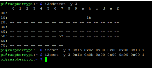
Does i2cdetect -y 3 show the DLP2000 controller? You should see 1b cell filled in. If that cell shows -- then you don’t have the I2C bus hooked up right.
If you do see the controller, run i2cset -y 3 0x1b 0x0c 0x00 0x00 0x00 0x13 i to set the input resolution to 864x480 (assuming that’s the resolution you set in your config.txt), then i2cset -y 3 0x1b 0x0b 0x00 0x00 0x00 0x00 i to set the input to the parallel bus.
Hi, thanks for the quick response!
This is what I once again did to try to get it working, still it doesn’t work…
PS I tested my wiring for continuity to make sure it was all conected properly
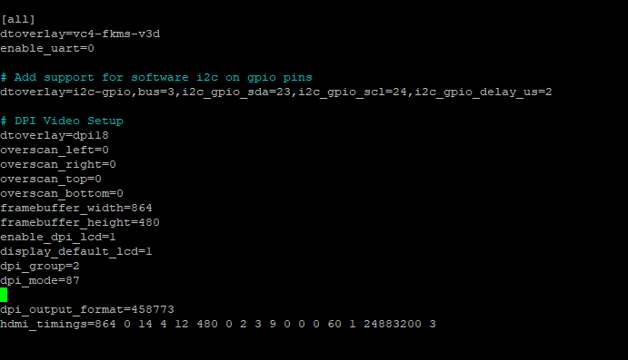
Here is my config.txt (the part that is relevant):
#Uncomment some or all of these to enable the optional hardware interfaces
dtparam=i2c_arm=on
#dtparam=i2s=on
#dtparam=spi=on
#Uncomment this to enable infrared communication.
#dtoverlay=gpio-ir,gpio_pin=17
#dtoverlay=gpio-ir-tx,gpio_pin=18
#Additional overlays and parameters are documented /boot/overlays/README
#Enable audio (loads snd_bcm2835)
dtparam=audio=on
[pi4]
#Enable DRM VC4 V3D driver on top of the dispmanx display stack
#dtoverlay=vc4-fkms-v3d
#max_framebuffers=2
[all]
dtoverlay=vc4-fkms-v3d
enable_uart=0
#Add support for software i2c on gpio pins
dtoverlay=i2c-gpio,bus=3,i2c_gpio_sda=23,i2c_gpio_scl=24,i2c_gpio_delay_us=2
#DPI Video Setup
dtoverlay=dpi18
overscan_left=0
overscan_right=0
overscan_top=0
overscan_bottom=0
framebuffer_width=854
framebuffer_height=480
enable_dpi_lcd=1
display_default_lcd=1
dpi_group=2
dpi_mode=87
dpi_output_format=458773
hdmi_timings=854 0 14 4 12 480 0 2 3 9 0 0 0 60 0 32000000 3
Ok, so it looks like your I2C bus is wired correctly, and you’re able to talk to the controller.
Try running i2cset -y 3 0x1b 0x0c 0x00 0x00 0x00 0x1b i to set the resolution to 640x360, and i2cset -y 30x1b 0x0b 0x00 0x00 0x00 0x01 i to set the input to the built-in test patterns. Change the displayed test pattern with i2cset -y 3 0x1b 0x11 0x00 0x00 0x00 $PATTERN i where $PATTERN is one of
-
0x00for a fine checkerboard -
0x01for solid black -
0x02for solid white -
0x03for solid green -
0x04for solid blue -
0x05for solid red -
0x06for vertical lines -
0x07for horizontal lines -
0x08for fine vertical lines -
0x09for fine horizontal lines -
0x0afor diagonal lines -
0x0bfor vertical grey gradient -
0x0cfor horizontal grey gradient -
0x0dfor a checkerboard
If the test pattern works, then double check your DPI bus wires. After trying the test patterns, you’ll need to re-run the i2cset commands from earlier to change the resolution to 864x480 and use the parallel bus input.
I also see a typo in your config.txt settings. You have a horizontal resolution (width) of 854 but you want 864. You also have the wrong pixel frequency in the hdmi_timings setting. Try using framebuffer_width=864 and hdmi_timings=864 0 14 4 12 480 0 2 3 9 0 0 0 60 1 24883200 3.
See a TI support thread, the programmer’s guide for the DLP controller, and the Raspberry PI DPI documentation.
Hi, thanks for the extensive response!
I was able to set the test paterns and see them being projected. I also changed the config.txt to the parameters you told me were wrong, still I had no luck. I did a re-run to change the parameters back after setting the test patterns. After setting the resolution the last testpatern started flickering, next I ran the command to use the parallel bus but the only thing that happened was the tespatern stopping to flicker, nothing else… Could it be possible that i2c-1 is messing with the parrallel bus (i2c-1 and i2c-3 are visible after running ls /dev)?
Yes, the hardware i2c-1 bus conflicts with V-SYNC and H-SYNC DPI pins so does need to be turned off. That’s why you enabled the i2c gpio driver on pins 23 and 24 (unused in DPI 18-bit mode).
I’m sorry but I am not realy able to find how to disable these, can you guide me where to look. Everything I find is how to disable i2c entirely.
Ok, I found how to disable i2c-1. Still it doesn’t work. I am 100% sure my wiring is correct.
This is what I use on my Pi4
[all]
#dtoverlay=vc4-fkms-v3d

#dtoverlay=i2c-gpio,bus=6,i2c_gpio_sda=23,i2c_gpio_scl=24,i2c_gpio_delay_us=2
dtoverlay=i2c6,pins_22_23

dtoverlay=dpi18
#dtoverlay=dpi24
overscan_left=0
overscan_right=0
overscan_top=0
overscan_bottom=0

## Use a custom DPI mode
dpi_group=2
dpi_mode=87

enable_dpi_lcd=1
display_default_lcd=1

## Should this really be 864x480? Native for the DMD should be 640x360
#framebuffer_width=864
#framebuffer_height=480
framebuffer_width=640
framebuffer_height=360

### https://www.raspberrypi.org/documentation/hardware/raspberrypi/dpi/README.md
## These are for dpi18
dpi_output_format=458773
#dpi_timings=864 0 14 4 12 480 0 2 3 9 0 0 0 60 1 24883200 3
dpi_timings=640 0 14 4 12 360 0 2 3 9 0 0 0 60 1 13824000 3
## These are for dpi24
#dpi_output_format=458775
#dpi_timings=864 0 14 4 12 480 0 2 3 9 0 0 0 60 1 24883200 3
To use it on a Pi0, you would want to comment the dtoverlay=i2c6,pins_22_23 line and uncomment the dtoverlay=i2c-gpio,bus=2,i2c_gpio_sda=23,i2c_gpio_scl=24,i2c_gpio_delay_us=2 line. Note that I’m using I2C bus 6, not 3, because on the Pi4 there’s a hardware I2C bus on those pins. That doesn’t exist on the Pi0 so you have to use the GPIO driver instead. If you want to still use bus 3, change the bus paramter on the i2c-gpio dtoverlay and change the BUS= Environment variable below.
Then create /etc/systemd/system/dlp.service as
[Unit]
Description=DLPDLCR2000EVM setup

[Service]
Type=oneshot
RemainAfterExit=yes
# Which I2C bus to use
Environment="BUS=6"
# Set resolution to 640x360
ExecStartPre=/usr/sbin/i2cset -y $BUS 0x1b 0x0c 0x00 0x00 0x00 27 i
# All LEDs on
ExecStartPre=/usr/sbin/i2cset -y $BUS 0x1b 0x16 0x00 0x00 0x00 0x07 i
# Set input to parallel bus
ExecStart=/usr/sbin/i2cset -y $BUS 0x1b 0x0b 0x00 0x00 0x00 0x00 i

# Set input to test pattern
ExecStop=/usr/sbin/i2cset -y $BUS 0x1b 0x0b 0x00 0x00 0x00 0x01 i
# Set test pattern to black
ExecStopPost=/usr/sbin/i2cset -y $BUS 0x1b 0x11 0x00 0x00 0x00 0x01 i
# All LEDs off
ExecStopPost=/usr/sbin/i2cset -y $BUS 0x1b 0x16 0x00 0x00 0x00 0x00 i
[Install]
WantedBy=multi-user.target
After making those changes, reboot, and run sudo systemctl start dlp to configure the DLP2000. If you want this to happen on boot, run sudo systemctl enable dlp. Run sudo systemctl stop dlp to configure the DLP2000 to a black screen, and turn off the LEDs.
Also note that I’m using 640x360, the native resolution of the DMD in the DLP2000, rather than 864x480. Some software may not like the lower resolution as much, but it means the DLP2000 doesn’t have to rescale the image. It also means less data being sent per frame, so signal integrity is a little better with flying wires.
If I might chime in here I am also using the pi4. Ultimately I coppied text from a working config file from a forum to get my DLP2000 working. I also remember people saying that if your gpio jumper wires are too long it can create issues. Adding more ground jumpers has also been reported to help. Good luck!